Parameter
|
Platform solution |
A41@WH M-star SSC30KQ+SC450 |
|
sensor |
4MP 1/1.8 ‘ the BSI back-illuminated target surface large Sensor ; |
|
system structure |
Dual-core A7 1.2GHz ; |
|
Image video |
description |
|
Smart coding |
Support group basis mode, advanced mode, reducing the storage footprint ; |
|
Video processing |
H.264 and H.265 video coding; Support three streams : main stream, auxiliary stream , and third streams ; |
|
Standard |
2560*1440@25 , 2304*1296@25 , 1920*1080@25 ; |
|
Resolution |
Mainstream: 2560*1440 , 2304*1296 , 1080P ; Auxiliary stream: 720P , D1 ( default ) , 640*360 , 2CIF , CIF ; Third stream: D1 , 640*360 , 2CIF , CIF ( default ) ; |
|
OSD |
Support date and time OSD , customize the OSD , serial OSD , Ethernet port OSD , most more than 8 pcs OSD ; |
|
Privacy mask |
It supports up to 4 zones ; |
|
Regional enhancement |
It supports up to 8 zones ; |
|
Wide dynamic |
Support optical wide dynamic ; |
|
Noise reduction |
Support 2D , 3D noise reduction ; |
|
shutter |
Support automatic / manual mode ; Support low smear mode ; Support indoor 50/60Hz shutter mode to suppress power frequency flicker ; |
|
Scene mode |
Support transparent (default) , bright, standard , San scene mode selection, image adjustment style preferences ; |
|
software |
description |
|
Business functions |
Support Web configuration ; Support OSD configuration, image configuration and other services ; Support capture the timing, capture time interval, alarm linkage shots, and through e-mail, the FTP , etc. The image alarm reporting; PPPOE /DHCP/ Static IP acquisition method ; Support multiple platform SDK development kits for secondary development ; Support high-definition audio and video synchronization preview, two-ways voice intercom ; Support motion detection , occlusion detection, sound detection, linkage APP to achieve mobile phone push alarm ; |
|
intelligent |
Support Depth intelligent Perimeter, support vehicle / non-vehicle / person classification of cross-border detection , enter the area , leaving the region , the region’s invasion 4 kinds behavior detection ; |
|
Sound and light warning |
Support, active alarms after detected humanoid, warning lights and voice alarm linkaged. |
|
upgrade |
Support local upgrade of WEB interface ; Support GuardTools batch upgrade ; Support cloud upgrade ; |
|
Control lights |
Support 1 way warm light PWM linear dimming ; |
|
Client |
Support mobile APP video preview ( IOS , Android ) ; Support PC client ‘s local management of IPC , realize multi-channel IPC live broadcast, local hard disk storage, etc .; |
|
custom made |
Support personalized customization, you can customize the model#, Logo , image scene mode or parameters, OSD , default alarm audio; |
|
Audio |
Description |
|
Audio processing |
Support G.711U and G.711A encoding and decoding standards; Support noise suppression; |
|
Audio output |
Maximum support for 64kbps transmission ; |
|
The internet |
description |
|
I P acquisition method |
PPPoE , full Netcom (enabled by default), DHCP , static IP address ; |
|
protocol |
Support IPv4 , IP v6 , H TTPS , TCP , UDP , DHCP , RTP , RTSP , DNS , DDNS , NTP , port mapping and other network protocols ; |
|
compatibility |
Support ONVIF standard protocol, realize video preview and video recording of mainstream third-party NVR and PC client ; Support GB \T28181 national standard agreement; |
|
Interface characteristics |
description |
|
Network status indicator |
Support ; |
|
Audio input interface |
Supports 2 -ways MIC input ; |
|
Audio output interface |
Support 1 channel Line out output ; |
|
Network Interface |
Support 100M network port ; |
|
RS485 interface |
Support ; |
|
RS232 interface |
Support ; |
|
hardware |
description |
|
Board thickness |
Sensor board 2 mm ; coding board 1.6mm ; |
|
weight |
The net weight is about 0.08 kg ( 0.11lb ) ; |
|
working environment |
-30℃~60℃(-22°F~140°F) |
|
Board size |
38 mm* 38mm , 38 standard single board structure ; |
|
power supply |
DC12V±25% , support anti-reverse connection, overvoltage, overcurrent protection, input short circuit protection ; |
|
reliability |
7*24 hours -30 ℃ ~ 60 ℃ high and low temperature cycle test is stable and reliable ; Power port 2KV lightning protection, network port 4KV lightning protection, in line with national and international standards ; |
Port definition (the dot is the first pin)
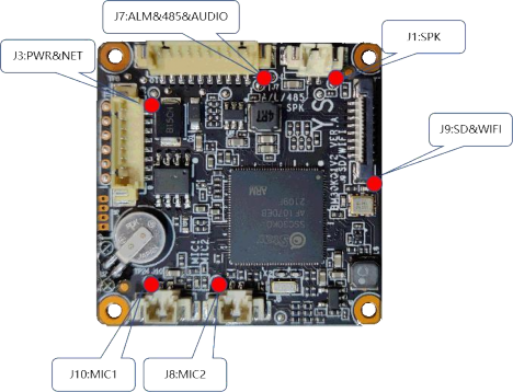
Figure 1 Schematic diagram of encoder board interface
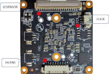
Figure 2 Schematic diagram of S ENSOR board interface
|
Silk screen number |
Pin number |
Interface definition |
Function description |
Signal direction |
Level |
Description |
|
J1 |
Reserved |
|||||
|
J 3 |
1 |
VDD12V_IN |
Total power input |
enter |
12V |
Power connector |
|
2 |
GND |
Total power ground |
GND |
0V |
||
|
3 |
RESET |
Reset signal |
enter |
0/ 3.3V |
Reset signal |
|
|
4 |
LED_ACT |
Network signal status indicator |
/ |
0/ 3.3V |
Signal status indicator |
|
|
5 |
TRD0_P |
Network data sending differential signal positive |
Output |
/ |
Ethernet interface |
|
|
6 |
TRD0_N |
Network data transmission differential signal negative |
Output |
/ |
||
|
7 |
TRD1_P |
Network data receiving differential signal positive |
enter |
/ |
||
|
8 |
TRD1_N |
Network data receiving differential signal negative |
enter |
/ |
||
|
J 4 |
1 |
Reserved |
||||
|
2 |
IR_CTRL_1 |
Photosensitive control output PWM1 |
Output |
0/3.3V |
Soft light-sensitive fill light signal |
|
|
3 |
IR_CTRL_2 |
Photosensitive control output PWM2 |
Output |
0/3.3V |
||
|
4 |
GND |
Ground |
GND |
0V |
||
|
J 5 |
1 |
ALM_IN2 |
Alarm Input |
Input |
0/3.3V |
Reserved |
|
2 |
ALM_OUT2 |
Reserved |
||||
|
3 |
UART2_TXD |
UART 2 data transmission signal |
Output |
0/ 3.3V |
UART signal |
|
|
4 |
UART2 _ RXD |
UART 2 data receiving signal |
enter |
0/ 3 .3V |
||
|
5 |
GND |
Ground |
GND |
0V |
||
|
6 |
485_EN2 |
RS485 enable control |
Output |
0 /3.3 V |
RS485 signal |
|
|
7 |
FAN_EN |
Output |
0 /3.3 V |
Reserved |
||
|
8- 10 |
Reserved |
|||||
|
J 7 |
1 |
ALM_IN1 |
Alarm Input |
Input |
0/3.3V |
|
|
2 |
Reserved |
|||||
|
3 |
ALM_OUT1 |
Alarm Output |
Output |
0/3.3V |
||
|
4 |
Reserved |
|||||
|
5 |
RS485_A |
RS485 data positive |
Input / output |
0 /3.3 V |
RS485 signal |
|
|
6 |
RS485_B |
RS485 data negative |
Input / output |
0 /3.3 V |
||
|
7 |
GND |
Ground |
GND |
0V |
||
|
8 |
Reserved |
audio signal |
||||
|
9 |
GND |
Ground |
GND |
0V |
||
|
1 0 |
SPK_OUT |
LINE _ OUT output |
Output |
Output/ 2.54Vpp |
||
|
J8 |
1 |
MIC_IN_ L |
MIC1 input signal |
enter |
/ |
MIC1 |
|
2 |
GND |
Ground |
GND |
0V |
||
|
J 9 |
Reserved |
|||||
|
J10 |
1 |
MIC_IN_ R |
MIC2 input signal |
enter |
/ |
MIC2 |
|
2 |
GND |
Ground |
GND |
0V |
||
|
2 , SENSOR board interface definition |
||||||
|
J 1 |
1 |
OUT1 |
IR-CUT signal + |
Input / output |
0/ 5V |
IR_CUT interface |
|
2 |
OUT2 |
IR-CUT signal – |
Input / output |
0/ 5V |
||
|
J 4 |
Reserved |
|||||