Parameter
| Platform solution | E41@WH M-star SSC377+SC450AI |
| system structure | Flash 8MB, DDR2 64MB; Cortex – A 35 1.0G Hz |
| sensor | 4MP 1 /1.8 ” Target surface |
| intelligent | describe |
| Mixed row detection | support;
Including humanoids, motor vehicles, and non-motor vehicles |
| Sound and light alarm | White light mode: White light full-color image at night. After mixed row detection triggers an alarm, it can be linked to voice and light alarms. |
| image video | describe |
| video processing | H.264, H.265 video encoding; |
| Standard | 2880 * 1620 @ 25 , 2560*1440@2 5 , 2304*1296@2 5 , 1920*1080@25 |
| resolution | Main stream: 2880 * 1620 , 2560*1440, 2304*1296, 1080P
Substream: D1 (default), 640*360, 2CIF, CIF |
| OSD | Support time OSD , custom OSD , up to 4 |
| privacy mask | Supported, up to 4 |
| area enhancement | Supported, up to 8 |
| wide dynamic range | Support digital wide dynamic range |
| Noise reduction | Support 2D , 3D noise reduction |
| shutter | Support automatic/manual mode
Support low smear mode Supports indoor 50/60Hz shutter mode to suppress power frequency flicker |
| scene mode | Supports three scene mode selections: transparent (default), bright, and standard, and adjusts image style preferences |
| software | describe |
| Business functions | Support web configuration
Supports OSD configuration , image configuration and other services Supports multiple platform SDK development kits for secondary development Supports high-definition audio and video synchronization preview and two-way voice intercom Support motion detection, linkage APP to achieve mobile phone push alarm Supports mixed row detection, supports linkage capture, and reports captured pictures to NVR and APP |
| Control lights | Support soft photosensitive light control |
| upgrade | Support local upgrade through WEB interface
Support GuardTools batch upgrade Support cloud upgrade |
| client | Support mobile APP video preview (IOS, Android), upgrade, mixed row settings, alarm sound upload and other functions
Support local management of IPC by PC client, realize multi-channel IPC live playback, local hard disk storage, etc. |
| custom made | Supports customized model, logo, default parameters, and IPC default language |
| Audio | describe |
| audio processing | Support G.711u, G.711a codec standards
Supports noise suppression |
| Audio output | Maximum support 64kbps transmission |
| network | describe |
| How to obtain IP | Full Netcom (enabled by default), DHCP, static IP address |
| protocol | Supports network protocols such as IPv4, TCP, UDP, DHCP, RTP, RTSP, DNS, DDNS , NTP, port mapping, etc.; |
| compatibility | Supports the ONVIF standard protocol to enable video preview and recording of mainstream brand NVRs and PC clients. |
| hardware | describe |
| Plate thickness | 1.6mm |
| working environment | – 30℃ ~ 60℃(-22 ° F~140 ° F) |
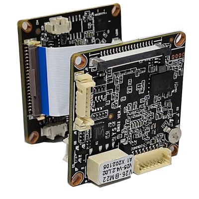
| Plate size | 38*38 standard size module split board |
| power supply | DC12V , supports anti-reverse connection protection |
| reliability | 7*24 hours -30℃-60℃ high and low temperature cycle test is stable and reliable
2KV lightning protection for the power port and 4KV lightning protection for the network port, in line with national and international standards |
Interface definition (coding board) (the dot is the first pin)
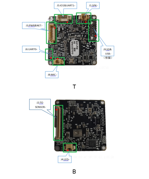
Definition of each pin of the interface
| Silk screen number | Pin number | Interface definition | Function description | Signal direction | level | illustrate |
| J1 | 1 | SPK_OUT_1 | speaker output | output | / | speaker interface |
| 2 | SPK_OUT_2 | speaker output | output | / | ||
| J 2 | 1 | NC | \ | \ | \ | Power interface |
| 2 | GND | land | GND | 0V | ||
| 3 | VDD3V3 | Power Output | output | 3.3V | ||
| 4 | VDD3V3 | Power Output | output | 3.3V | ||
| 5 | GND | land | GND | 0V | ||
| 6 | SEN_RST_N _ | S ENSOR reset signal | output | 0V /1.8V | SENSOR reset | |
| 7 | NC | \ | \ | \ | ||
| 8 | GND | land | GND | 0V | ||
| 9 | I2C_SCL _ | I2C clock signal | output | 1.8V | I2C signal | |
| 1 0 | I 2C_SDA | I2C data signal | input Output | 1.8V | ||
| 1 1 | NC | \ | \ | \ | ||
| 1 2 | NC | \ | \ | \ | ||
| 1 3 | NC | \ | \ | \ | ||
| 1 4 | NC | \ | \ | \ | ||
| 15 | GND | 地 | GND | 0V | ||
| 16 | NC | \ | \ | \ | ||
| 17 | NC | \ | \ | \ | ||
| 18 | GND | 地 | GND | 0V | ||
| 19 | NC | \ | \ | \ | ||
| 20 | NC | \ | \ | \ | ||
| 21 | NC | \ | \ | \ | ||
| 22 | NC | \ | \ | \ | ||
| 23 | NC | \ | \ | \ | ||
| 24 | NC | \ | \ | \ | ||
| 25 | NC | \ | \ | \ | ||
| 26 | NC | \ | \ | \ | ||
| 2 7 | GND | land | GND | 0V | MIPI signal | |
| 2 8 | MIPI_CH3_N | MIPI data channel 3 negative | enter | / | ||
| 2 9 | MIPI_CH3_P | MIPI data channel 3 positive | enter | / | ||
| 3 0 | MIPI_CH2_N | MIPI data channel 2 negative | enter | / | ||
| 3 1 | MIPI_CH2_P | MIPI data channel 2 positive | enter | / | ||
| 3 2 | MIPI_CH1_N | MIPI data channel 1 negative | enter | / | ||
| 3 3 | MIPI_CH1_P | MIPI data channel 1 positive | enter | / | ||
| 3 4 | MIPI_CH0_N | MIPI data channel 0 negative | enter | / | ||
| 3 5 | MIPI_CH0_P | MIPI data channel 0 positive | enter | / | ||
| 3 6 | GND | land | GND | 0V | ||
| 3 7 | MIPI_DCK_N | MIPI clock negative | enter | / | ||
| 3 8 | MIPI_DCK_P | MIPI clock positive | enter | / | ||
| 3 9 | GND | land | GND | 0V | SENSOR clock | |
| 4 0 | CLK_SENSOR | S ENSOR clock | output | / | ||
| J 3 | 1 | VDD12V | power input | enter | 12V | Power interface |
| 2 | GND | land | G N | 0V | ||
| 3 | NC | \ | \ | \ | Network indicator light | |
| 4 | LED_ACT | Network indicator light | output | / | ||
| 5 | TRD0_P | Network differential transmission signal positive | output | / | Network Differential Signaling
interface |
|
| 6 | TRD0_N | Network differential transmit signal negative | output | / | ||
| 7 | TRD1_P | The network differential input signal is positive | enter | / | ||
| 8 | TRD1_N | Network Differential Input Signal Negative | enter | / | ||
| J 4 | 1 | W HLED+ | White light LED control + | output | / | LED interface |
| 2 | LED- _ | LED- _ | output | / | ||
| J 5 | 1 | IO1 _ | IO interface 1 | input Output | 0 /3.3V | Functional interface |
| 2 | I O2 | IO interface 2 | input Output | 0 /3.3V | ||
| 3 | UART1_TXD | U ART1 data transmission signal | output | 0 /3.3 V | ||
| 4 | UART1_RXD | U ART1 data reception signal | enter | 0 / 3.3V | ||
| 5 | GND | land | GND | 0V | ||
| J6 | 1 | VDD3V3 | Power Output | output | 3.3V | Debug interface |
| 2 | UART0_TXD | U ART 0 data transmission signal | output | 0 /3.3 V | ||
| 3 | UART0_RXD | U ART 0 data reception signal | enter | 0 / 3.3V | ||
| 4 | GND | land | GND | 0V | ||
| J 8 | 1 | MIC_IN | M IC input signal | enter | / | MIC input interface |
| 2 | GND | land | GND | 0V | ||
| J 9 | 1 | 4G_POWER_EN _ | 4G power enabled | output | 1.8V | 4G interface (reserved) |
| 2 | USB_DP _ | USB signal positive | input /output | / | ||
| 3 | USB_DM _ | USB signal negative | input /output | / | ||
| 4 | SW_RST _ | reset | enter | 0 / 3.3V | reset interface | |
| 5 | GND | land | GND | 0V | ||
| 6 | SD_CLK _ | SD card clock signal | output | 0/3.3V | SD card signal (reserved) |
|
| 7 | GND | land | GND | 0V | ||
| 8 | S D_CD | SD card detection signal | input | 0/3.3V | ||
| 9 | S D_D0 | SD card data D 0 | input Output | 0/3.3V | ||
| 1 0 | S D_D1 | SD card data D 1 | input Output | 0/3.3V | ||
| 1 1 | S D_D2 | SD card data D 2 | input Output | 0/3.3V | ||
| 1 2 | S D_D3 | SD card data D 3 | input Output | 0/3.3V | ||
| 1 3 | SD_CMD _ | SD card commands | input /output | 0/3.3V | ||
| 1 4 | SD_POWER _ | SD card power enable | output | 0/3.3V | ||
| 1 5 | GND | land | GND | 0V | Power interface | |
| 1 6 | VDD3V3 _ | Power Output | output | 3.3V |
Interface definition (Sensor board) (the dot is the first pin)
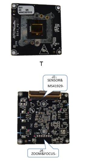
Definition of each pin of the interface
| Silk screen number | Pin number | Interface definition | Function description | Signal direction | level | illustrate |
| J 2 | 1 | CLK_SENSOR | S ENSOR clock | enter | / | S ENSOR clock |
| 2 | GND | land | GND | 0V | ||
| 3 | MIPI_DCK_P | MIPI clock positive | output | / | MIPI signal | |
| 4 | MIPI_DCK_N | MIPI clock negative | output | / | ||
| 5 | GND | land | GND | 0V | ||
| 6 | MIPI_CH0_P | MIPI data channel 0 positive | output | / | ||
| 7 | MIPI_CH0_N | MIPI data channel 0 negative | output | / | ||
| 8 | MIPI_CH1_P | MIPI data channel 1 positive | output | / | ||
| 9 | MIPI_CH1_N | MIPI data channel 1 negative | output | / | ||
| 1 0 | MIPI_CH2_P | MIPI data channel 2 positive | output | / | ||
| 1 1 | MIPI_CH2_N | MIPI data channel 2 negative | output | / | ||
| 1 2 | MIPI_CH3_P | MIPI data channel 3 positive | output | / | ||
| 1 3 | MIPI_CH3_N | MIPI data channel 3 negative | output | / | ||
| 1 4 | GND | land | GND | 0V | ||
| 1 5 | NC | \ | \ | \ | ||
| 1 6 | SPI_CLK | SPI clock | enter | / | M S41929 signal | |
| 1 7 | SPI_MOSI | SPI data | enter | / | ||
| 1 8 | SPI_MISO | SPI data | output | / | ||
| 1 9 | SPI_CS | chip select signal | enter | / | ||
| 2 0 | RSTB_MS41929 | initialization signal | enter | / | ||
| 2 1 | NC | \ | \ | \ | ||
| 2 2 | VD_MS41929 | Adjust focus magnification image synchronization signal | enter | \ | ||
| 2 3 | GND | land | GND | 0V | ||
| 2 4 | MIC_IN_R | MIC signal R | output | \ | M IC signal | |
| 2 5 | MIC_IN_L | MIC signal L | output | \ | ||
| 2 6 | GND | land | GND | 0V | ||
| 2 7 | ICR_AIN2 | I CR signal 2 | enter | \ | I CR signal | |
| 2 8 | ICR_AIN1 | I CR signal 1 | enter | \ | ||
| 2 9 | NC | \ | \ | \ | ||
| 3 0 | NC | \ | \ | \ | I2C interface | |
| 3 1 | I2C_SDA | I2C data | enter | / | ||
| 3 2 | I2C_SCL | I2C clock | input Output | 1.8V/0V | ||
| 3 3 | GND | land | GND | 0V | S ENSOR reset | |
| 3 4 | PWM_SEN_N | POWER DOWN signal | enter | / | ||
| 3 5 | SEN_RST_N | SENSOR reset signal | enter | / | ||
| 3 6 | GND | land | GND | 0V | Power interface | |
| 3 7 | VDD3V3 | Power input | input | 3.3V | ||
| 3 8 | VDD3V3 | Power input | input | 3.3V | ||
| 3 9 | GND | land | GND | 0V | ||
| 4 0 | VDD5V | Power input | input | 5.0V | ||
| J 4 | 1 | ZOOM1_N _ | ZOOM stepper motor control | output | / | Lens mount |
| 2 | ZOOM1_P _ | ZOOM stepper motor control | output | / | ||
| 3 | FOCUS1_P _ | Focus stepper motor control | output | / | ||
| 4 | FOCUS1_N _ | Focus stepper motor control | output | / | ||
| 5 | FOCUS2_P _ | Focus stepper motor control | output | / | ||
| 6 | FOCUS2_N _ | Focus stepper motor control | output | / | ||
| 7 | ZOOM2_P _ | ZOOM stepper motor control | output | / | ||
| 8 | ZOOM2_N _ | ZOOM stepper motor control | output | / |